Back to the main page Back to category Synthesizers
musical instrument details
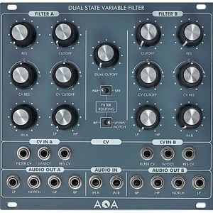
AQA Elektrix Dual State Variable Filter Module
Estimated price for orientation: 509 $
Category: Synthesizers
Class:
Description Condition: New: A brand-new, unused, unopened, undamaged item in its original packaging (where packaging is applicable). Packaging should be the same as what is found in a retail store, unless the item is handmade or was packaged by the manufacturer in non-retail packaging, such as an unprinted box or plastic bag. See the seller's listing for full details. See all condition definitions- opens in a new window or tab ... Read moreabout the condition Brand: AQA ElektriX MPN: AQADSVF EAN: Does not apply
Variable filter synth module in Eurorack format The Dual 12 dB State Variable VCF module contains two 12dB state variable multimode VCF's A and B, which both offer a Low-pass, a Bandpass and a High-pass filtered output of the input signal as well as a Notch-output, simultaneously.The notch output is just a crossfaded HP and LP signal, so the corresponding knob can blend continuously between LP (knob fully counter-clockwise) over Notch (knob's 12'o clock position) to HP (knob fully clockwise). Both filters A and B can be independently controlled, there is a cut-off and a resonance knob for each of them. The cut-off of both filters can also be controlled together by another "main"-cut-off-knob, so turning that knob, both filter cut-offs will be controlled in "gang-mode". All audio and CV inputs are normalized from Filter A=>B. Both filters A and B can be routed in parallel or serial configuration using the "ser/par-switch" (A=>B or A II B). Both filters A and B have CV inputs for cut-off and resonance each, which can be attenuated separately, so you could use one CV for controlling both filters simultaneously by plugging the control CV into the CV input for filter A, since the CV-inputs are normalized. Both filters could be modulated by the CV in the same direction or in inverse directions by different amounts. Additionally, both filters A and B have a CV input for controlling the cut-off using nearly a Volt/Octave characteristic. In serial mode, the signal flow is from Filter A=>B. You can use a switch ("HP/LP/Notch / BP") to select either the LP/Notch/HP-output (chosen by the "LP-HP - knob" of Filter A) or the BP - output of filter A. Both Input - attenuator's (Filter A and B) are active and can be used to adjust the signal level. Please be careful! The module can produce very loud signals, especially under high resonance settings of both filters and even more, when both cut-off-settings of Filter A and B are very close to each other.Functions:
- Audio Input jack SVF A & B - Input for the Audio Signal
- Cutoff CV Input jack SVF A & B - CV input for cutoff frequency, attenuverted by CV Cutoff Pot
- CV Input jack SVF A & B - CV input for frequency control, attenuated by CV Pot
- V/Oct Input jack - CV input for Volt/Octave Range, unattenuatedMeasures: 26 TEPower consumption: -12V 50mA / +12V 53mAFeatures Input attenuators for each SVFEach SVF cut-off frequency can be independently controlled by knobBoth cut-off frequencies can be controlled at once with a common cut-off knobAttenuated cut-off CV input for each SVFEach SVF resonance can be controlled by knob separatelyEach SVF resonance can be controlled by an external control voltage individuallyLP/BP/HP Outputs available for each SVFVariable Balance Notch Output for each SVF (Oberheim SEM)1V/Oct CV Inputs for each SVFRouting Mode for each SVF switchable: parallel & serialAudio and CV inputs are normalized from SVF B on SVF ASpecifications
Description
| Condition: | New: A brand-new, unused, unopened, undamaged item in its original packaging (where packaging is applicable). Packaging should be the same as what is found in a retail store, unless the item is handmade or was packaged by the manufacturer in non-retail packaging, such as an unprinted box or plastic bag. See the seller's listing for full details. See all condition definitions- opens in a new window or tab ... Read moreabout the condition | Brand: | AQA ElektriX |
| MPN: | AQADSVF | EAN: | Does not apply |
Variable filter synth module in Eurorack format The Dual 12 dB State Variable VCF module contains two 12dB state variable multimode VCF's A and B, which both offer a Low-pass, a Bandpass and a High-pass filtered output of the input signal as well as a Notch-output, simultaneously.The notch output is just a crossfaded HP and LP signal, so the corresponding knob can blend continuously between LP (knob fully counter-clockwise) over Notch (knob's 12'o clock position) to HP (knob fully clockwise). Both filters A and B can be independently controlled, there is a cut-off and a resonance knob for each of them. The cut-off of both filters can also be controlled together by another "main"-cut-off-knob, so turning that knob, both filter cut-offs will be controlled in "gang-mode". All audio and CV inputs are normalized from Filter A=>B. Both filters A and B can be routed in parallel or serial configuration using the "ser/par-switch" (A=>B or A II B). Both filters A and B have CV inputs for cut-off and resonance each, which can be attenuated separately, so you could use one CV for controlling both filters simultaneously by plugging the control CV into the CV input for filter A, since the CV-inputs are normalized. Both filters could be modulated by the CV in the same direction or in inverse directions by different amounts. Additionally, both filters A and B have a CV input for controlling the cut-off using nearly a Volt/Octave characteristic. In serial mode, the signal flow is from Filter A=>B. You can use a switch ("HP/LP/Notch / BP") to select either the LP/Notch/HP-output (chosen by the "LP-HP - knob" of Filter A) or the BP - output of filter A. Both Input - attenuator's (Filter A and B) are active and can be used to adjust the signal level. Please be careful! The module can produce very loud signals, especially under high resonance settings of both filters and even more, when both cut-off-settings of Filter A and B are very close to each other.Functions:
- Audio Input jack SVF A & B - Input for the Audio Signal
- Cutoff CV Input jack SVF A & B - CV input for cutoff frequency, attenuverted by CV Cutoff Pot
- CV Input jack SVF A & B - CV input for frequency control, attenuated by CV Pot
- V/Oct Input jack - CV input for Volt/Octave Range, unattenuatedMeasures: 26 TEPower consumption: -12V 50mA / +12V 53mAFeatures Input attenuators for each SVFEach SVF cut-off frequency can be independently controlled by knobBoth cut-off frequencies can be controlled at once with a common cut-off knobAttenuated cut-off CV input for each SVFEach SVF resonance can be controlled by knob separatelyEach SVF resonance can be controlled by an external control voltage individuallyLP/BP/HP Outputs available for each SVFVariable Balance Notch Output for each SVF (Oberheim SEM)1V/Oct CV Inputs for each SVFRouting Mode for each SVF switchable: parallel & serialAudio and CV inputs are normalized from SVF B on SVF ASpecifications