Back to the main page Back to category Synthesizers
musical instrument details
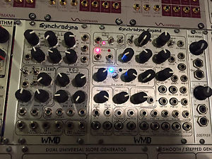
WMD SYNCHRODYNE PLUS SYNCHRODYNE EXPAND 2 modules Eurorack Modular Synthesizer
Estimated price for orientation: 590 $
Category: Synthesizers
Class:
Description Condition: Used: An item that has been used previously. The item may have some signs of cosmetic wear, but is fully operational and functions as intended. This item may be a floor model or store return that has been used. See the seller’s listing for full details and description of any imperfections. See all condition definitions- opens in a new window or tab ... Read moreabout the condition
THE ITEM WILL BE SENT FROM PERU NOT THE UK AS I MOVED HERE NOW. EXCELLENT SERVICE NEVER LOST A PACKAGE. WMD SYNCHRODYNE WITH SYNCHRODYNE EXPAND MODULE 2 MODULES IN TOTAL! ALL IN PERFECT SHAPE AND PERFECT WORKING CONDITION!--------ULTRA CHEAP!-------------------- I´LL COMBINE SHIPPING COST IF YOU BUY MORE MODULES!!! Check my other items for more modular , I'LL COMBINE SHIPPING COST. -------------------
wmd
synchrodyne
introducing the wmd synchrodyne, a multi part and multi use eurorack module for the creation and manipulation of audio. containing several pieces to a traditional synthesizer voice, the synchrodyne is a powerful addition to any subtractive oriented system. however, it is designed primarily as an experimental sound source/filter, intended to push the limits of modular synthesis...wmd style.features:
front end linear vca
switchable four stage wavefolder
tempco sawcore vco
linear (ac/dc) & expo (dc) fm
bipolar attenuators for fm
calibrated 1v/oct input
hard sync input
vco range ~.02hz - >=400khz
phase locked loop
pll frequency multiplier/divider
variable slew & damping in pll
switched capacitor filter
multimode filter output
-12 & -24 db/oct output taps
stable self-oscillation at -24db/oct
voltage control of filter resonance
single stage wavefolder on outs
expandable
14hp, ~60ma power draw
100% analog/discrete/cmossynchrodyne concept:
the synchrodyne is designed as a way to implement a switched capacitor filter (scf) chip without the use of a microcontroller to run the clock. we developed a fast analog vco that can drive the scf with a good range of frequency control. however, then the vco is dedicated to only running the filter. so we designed a frequency multiplier based around a phase locked loop ic (pll) to take the vco and multiply its frequency up so that the vco could be used as an audio source, while still controlling the filter. the scf has a frequency ratio of 50:1 or 100:1 clock frequency to output cutoff frequency. the pll allows for many ratios of input to output frequencies to be selected, making the vco useful as an audio source.the pll introduced its own challenges. taming the pll to stabilize at high multiplication ratios required us to develop a damping circuit. the damping and track speed controls cause the pll to have its own sound, sort of a self frequency modulation. we wanted the synchrodyne to distort nicely with audio input, and also to self-oscillate. we added single stage rectifiers to the -12db and -24db filter outputs for a more aggressive sound. we opted to develop a vca and wavefolder for the front end of the filter to further expand the palate of distortion and processing of the synchrodyne. we had more features to add, but space was limited and we didn't want to make an excessively expensive module, so we added two 14pin expansion headers for future development.vco controls and i/o:
the synchrodyne's vco is a traditional sawtooth core. it uses very modern parts to achieve the stability and speed necessary for driving the synchrodyne.1v/oct input - calibrated input for pitch control. the vco will track at least 5 octaves using this input. sync input - rising edge sawtooth reset/sync input. does not affect slope of sawtooth.coarse & fine knobs - coarse knob adjust the frequency of the vco throughout its full range. use the fine knob to tune the oscillator within approximately 1/3 octave range. exp fm - this input jack and bipolar attenuator provide exponential fm to the vco. this input is dc coupled.lin fm - this input jack and bipolar attenuator provide linear fm to the vco. this input can be dc or ac coupled. a jumper on the back enables dc coupling when in place. we recommend ac coupling to prevent frequency shift caused by the bipolar attenuator's offset voltage.saw output - the sawtooth output is available here. its level is approximately +-4.5 volts.pulse output - this output presents the rectangle wave necessary for driving the pll. it is not a 50% duty cycle square, but approximately 30%/70% as that provided the best performance for driving pll.pll controls and i/o:
the pll takes the rectangle wave from the vco and drives the filter.clk input - the pulse output from the vco is normaled here. plug in an external clock source to drive the pll with something else.multiply & divide switch knobs - these rotary switches adjust the frequency of the clock multiplier & divider inside the pll. adjust these to set the frequency ratio. higher multiplcation factors cause the pll to react slower to changes, especially at low input frequencies. phase delta output - this output represented by symbols is the result of the multiplication factor. it produces some self pwm as the pll stabilizes and will equal the input clock frequency if the pll is locked. this output provides an interesting self modulating audio or clock source.pll output - this is the output of the pll stage. it is the input frequency multiplied and divided by the set ratios.track speed knob - this controls the reaction speed of the pll in trying to keep up with changes to the input frequency. fully ccw it will introduce lots of glissando in the filter reaction. fully cw and it will over-track, causing the pll to respond faster than the input frequency. overtracking produces bursts of high frequency output and low frequency output.damping knob - this control reduces the rate of fluctuation while overtracking, damping the overtracking and increasing stability. more damping will be needed as higher ratios of frequency multiplication are selected. influence input and knob - this control acts directly with the track speed and damping controls in stabilizing the frequency of the pll. use a voltage source to modulate the pll signal. very complex modulations are possible by using influence with the internal vco and other controls.filter controls and i/o:
the core of the synchrodyne is a 4 pole (-24db/octave) switched capacitor filter circuit. the 2 pole output is tapped and provides a mellower filter sound. the synchrodyne will self-oscillate at high resonances on both outputs, however it is more prominent on the 4 pole output.the switched capacitor filter topology has a few interesting features. it is a sampled data construct, so at low cutoff frequencies, the filter will produce aliasing noise, similar to the sample rate reduction on the geiger counter. this topology is also very stable and accurate, allowing for predictable cutoff frequencies to be selected. across its entire range (.02 hz to 16khz) the filter will remain within +-0.2% of where it should be. in jack - insert signal to be filtered here.vca cv input and knob - when there is no input to the vca cv jack, the knob acts as an attenuator for the input signal. plugging into the vca cv jack causes the knob to act as an attenuator for the cv signal controlling the input vca.fold toggle - flipping this up causes the input vca to drive a four stage wavefolder. the output of the wavefolder then goes o the filter. the level of the input signal going into the filter from the wave-folder is adjustable with the blue trim-pot on the back of the synchrodyne. this will be broken out to the expansion.resonance knob - directly controls the resonance of the switched capacitor filter.resonance cv input and attenuator - this input will add to the primary resonance knob through the attenuator. use for animating the filter's resonance.100:1 - 50:1 ratio toggle - this controls the filter core's frequency ratio. there is one octave of difference between the two settings. at low frequencies, the 50:1 ratio will produce more aliasing/sampling distortion.lowpass / bandpass / highpass toggle - selects the output mode of both the 2 pole and 4 pole outputs.filter outputs - jacks for the 2 pole (-12db/oct) and 4 pole (-24db/oct) are available. please note that they are 180 degrees out of phase from each other. additionally, a single stage wave-folded output is available for both the 2 pole and 4 pole outputs. the wave-folded outputs provide another level of sonic depth to experiment with. the future expansion:
we plan to release an expansion for the synchrodyne breaking out a few features and adding cv control to a number more. the expansion module will provide dedicated -12db/octave outputs, access to the vca and 4 stage wavefolder (pre filter), standard wave-shapes for the vco (triangle, sine, pwm), voltage control over many of the pll functions (damping, track speed, frequency multiplication and division), it will serve as a second pll to be modulated with the primary one or usable separately. expect the expansion sometime in the summer of 2012.other notable things:
the synchrodyne is 14 hp
current consumption is around 60ma for the +12 rail; 50ma for the -12 rail
the majority of the audio circuitry runs at +-5 volts and uses high-speed rail to rail opamps
the depth from the back of the panel is roughly 40mm.wmd
synchrodyne expand
his is the wmd synchrodyne expand, we went a little crazy with it. but we figured that if you can grasp the original, you're the type that always wants to go deeper. so lets take this plunge together as we attempt to explain what it all means.synchrodyne expand concept:
the synchrodyne by itself is capable of a great deal, containing several modules in one, prepatched internally to create a vibrant range of sounds. it was difficult to cut many of the control capabilities from the synchrodyne to keep it within the scope of an analog switched-capacitor filter module. the expand lets us bring many of the little nuances of the synchrodyne to the patchable world. it is designed to be powerful and extremely dynamic when minimally patched, but when patch cords start flying around to be open and experimental. you may also use many of the parts of the synchrodyne and expand separately in various parts of your patches. the open architecture allows it to do many jobs, even small ones. vco2 / pll2:
vco2 contains an identical saw core oscillator as on the synchrodyne. the peripherals are slightly different, emphasizing different control points. the pll frequency multiplier is similar to that on the synchrodyne with many additional patch points.1v/oct input - calibrated input for pitch control. the vco will track at least 5 octaves using this input. this may be calibrated by the front mounted trim pot between the coarse and fine knobs.pwm input & knob - cv control over the pwm (pulse width modulation) of vco2. very powerful for controlling the filter core when both vcos are combined. control knob provides static pwm amount. it is added to cv signal when cv is applied.sync input - rising edge sawtooth reset/sync input. does not affect slope of sawtooth.coarse & fine knobs - coarse knob adjust the frequency of the vco throughout its full range. use the fine knob to tune the oscillator within approximately 1/3 octave range. exp fm - this input jack provides 1/3 v/octave exponential control to the vco core. lin fm - this input provides linear frequency control to the vco core. it is dc coupled.saw output - the sawtooth output is available here. its level is approximately +-4.5 volts.pwm output - presents the output of the pwm modulated waveform. pll input - this input runs into pll2, it is normaled from the pwm output of the vco. use an external vco to control the pll by patching here.pll output - square wave raw output of the pll frequency multiplier. this output is in a feedback loop with the vco2 multiply control to provide multiplication of the frequency. pll triangle output - this output is a hacked triangle wave from the pll core. it's not a perfect triangle but is close. it's great for softer sounds in the audio range.pc or in - this input is logical ored to the phase comparator on the pll. applying a clock or gate signal can produce frequency variance, destabilization or total melt down. very experimental input. track speed control & cv input - track speed is part of the pll cores self-stabilization of the phase locked loop. more track speed means that the pll will attempt to track the frequency more accurately and stabilize faster. tracking too fast can cause total breakdown of the loop and result in some unstable and interesting timbres. led shows the strength of the track speed. damping control & cv input - damping is the other half of the stabilization circuitry inside the pll core. higher damping means that frequency control circuit will resist change more. use this to tame high track speeds. cv input allows for external control of the damping. led shows the strength of the damping circuit. pc out - this is the phase comparator's direct output. it is a tri-state output (0v, 5v or high-impedance/floating). this is normaled to the track/damp circuitry to provide the control signal for the pll's frequency output. this output is intended to be run through a slew limiter and back into the pll ctrl or t/d in. though other uses may be found. t/d input - this is a direct input to the tracking damping circuitry. it normally expects a tri-state signal but it can handle other things. very experimental input. pll ctrl input - this input is the direct line to the pll frequency circuit. plugging voltages in to this will cause direct control over the pll and many of the prior circuits will be ignored including track/damp and multiply. very experimental and useful for further processing of the phase comparator signal.pll desync input - this input is a dc couple short circuit to the pll. a signal higher than 1v here will kill the pll requiring it to resynchronize with itself. pll2 range switch - this switch changes the maximum range of the pll by changing the pll's frequency generation capacitor. hi provides the full range. medium and low provide a much smaller range, limited to audio frequencies. medium and low also cause the pll triangle output to sound different.pwm/pll switch - this switch determines whether the pwm signal or the pll signal go to the vco2 section of the clock select switch. filter clock control:
this box in the top left of the synchrodyne expand controls the filter clock on the synchrodyne. there are three possible clock sources for the filter core. clock control switch - this toggle on the far right of the box selects which clock source runs the filter core. top position lets pll1 on the synchrodyne control the clock. bottom position lets pll2/vco2 control the clock. middle position combines the clocks and lets them fight each other. or / xor switch - this toggle switch controls how multiple clock signals are combined. xor mode combines the clocks in a fairly additive manner. or mode is more aggressive and gives each clock signal more power to disrupt the other signal. clk3 input - this jack provides an additional input to the filter core. it is combined in the mode chosen by the or / xor switch. led - shows the clock status directly. much of the time this will be too fast to see.pll1 cv inputs:
this small box contains inputs for track speed and damping for the pll in the synchrodyne.damping cv - this input gives cv control to damping on pll1. to achieve full damping (fully cw rotation of the knob on pll1), the damping knob on pll1 must be fully clockwise. this is because the cv control and knob are in series with each other. this jack is normaled to +5 volts so that it is always at a high damping, allowing the knob or the cv control to have an effect whether cv is used or not.track speed cv - this input provides cv control over track speed on pll1. this cv signal is in parallel with the track speed knob on the synchrodyne. therefore, minimum track speed is achieved with the knob fully ccw and 0v on the cv input. maximum track speed may be achieved by the knob or the cv input being cw or shown 5 volts respectively. pre filter compressor:
the synchrodyne's filter core can produce very dynamic material with high resonance, especially in 4 pole mode. so we added a pre filter compressor to reduce distortion inside the core. the concept here is a feedback compressor that reduces the signal level going into the core based on the level on the core's output. this is a vactrol based compressor.the signal seen by the compressor is a mix of the vca/fold switch and in2.ctrl switch - this switch determines where the compression circuit looks for waveform information. comp sc looks at the comp sc in jack. 2p looks at the selected 2 pole output from the synchrodyne's panel, and 4p looks at the selected 4 pole output. comp sc in - this input normally sees the signal from the compressor's output. this lets you compress the signal flowing to the filter core based on another signal. if nothing is plugged in, you have normal compression based on the level of the input signal.compression - this controls the overall amount of compression done to the input waveform. fully ccw will be no compression. fully cw will be close to limiting. amount of compression is indicated on the blue led.blue threshold trim pot - this trim pot between ctrl and comp attack allows you to change the threshold of compression. turn up for compression to come on sooner. this is similar to the compression control and was not necessary to bring out as a full control.comp attack - this sets the attack speed of the compressor. it works with the decay speed and has bearing on the overall amount of compression. comp decay - this sets the decay speed of the compressor. if it is too high and comp attack is not high enough, the compressor will not compress.comp out - this output produces the compressed signal for use elsewhere. it is normaled to the filter input.comp cv out - this is the cv control envelope signal as an output. filter 2:
filter 2 is a second switched capacitor filter. it is a 4-pole low pass type with an interesting resonance circuit. it resonates 180 degrees out of phase with the input signal. it will happily self resonate and makes a good sine wave oscillator.clk in - this input provides the high-speed clock to filter 2. it is normaled from the output of pll2. in -this is the signal input to the filter. it is normaled from the in 2 jack and attenuator. out - 4-pole low pass output of filter 2. clip out - amplified diode rectified output signal from the feedback resonance stage of filter 2. resonance knob - this controls the amount of resonance. it will self oscillate and this controls the level of oscillation. other inputs / outputs / controls:
filter in - this input runs directly to the filter core. it bypasses everything on the front end: vca, wavefolder, compressor, in2.in 2 to comp - this jack and attenuator provide a second input to the compressor and then to the filter core. it is normaled from the saw output of vco2.wf (wavefolder) level - this control replaces the blue trimmer on the back of the synchrodyne giving you direct control over the amplification of the wavefolded signal. vca out - direct out of the vca on the synchrodyne.wf out - direct out of the wavefolder on the synchrodyne.2p - 4p - subtractive output where 4p output is subtracted from the 2p output. produces a band-pass sort of sound. nicer at lower resonances. 2p notch - this is the notch output from the 2-pole filter on the synchrodyne. it is a true notch filter where resonance controls the width of the notch. higher resonances yield narrower notches. 4p notch - this output is not a true notch output. the 2-pole output (hp/bp/lp) is filtered by the last 2 poles of the filter internally, and the notch from that is output here. it is more of an elliptic output than a true notch because of this.-------------------- , i'll combine shipping cost for multiple items Please ask questions. - Do not pay immediately after winning , the shipping cost in the list is referencial only as every country has it's own cost that i can calculate in the Serpost website so please make questions. Check my feedback and bid with confidence , I've been selling gear at Ebay UK since 2002 and have a lot of experience in shipping gear.DO NOT PAY IMMEDIATELY AFTER WINNING THE ITEM , THE POSTAGE COST SHOWN IN THIS LIST IS ONLY A REFERENCE ( IT"S FOR SENDING TO GERMANY AS EXAMPLE) EVERY COUNTRY HAS A DIFFERENT COST PLEASE ASK THE COST FOR YOUR COUNTRY Thanks for reading and good luck
Description
| Condition: | Used: An item that has been used previously. The item may have some signs of cosmetic wear, but is fully operational and functions as intended. This item may be a floor model or store return that has been used. See the seller’s listing for full details and description of any imperfections. See all condition definitions- opens in a new window or tab ... Read moreabout the condition |
THE ITEM WILL BE SENT FROM PERU NOT THE UK AS I MOVED HERE NOW. EXCELLENT SERVICE NEVER LOST A PACKAGE. WMD SYNCHRODYNE WITH SYNCHRODYNE EXPAND MODULE 2 MODULES IN TOTAL! ALL IN PERFECT SHAPE AND PERFECT WORKING CONDITION!--------ULTRA CHEAP!-------------------- I´LL COMBINE SHIPPING COST IF YOU BUY MORE MODULES!!! Check my other items for more modular , I'LL COMBINE SHIPPING COST. -------------------
wmd
synchrodyne
introducing the wmd synchrodyne, a multi part and multi use eurorack module for the creation and manipulation of audio. containing several pieces to a traditional synthesizer voice, the synchrodyne is a powerful addition to any subtractive oriented system. however, it is designed primarily as an experimental sound source/filter, intended to push the limits of modular synthesis...wmd style.features:
front end linear vca
switchable four stage wavefolder
tempco sawcore vco
linear (ac/dc) & expo (dc) fm
bipolar attenuators for fm
calibrated 1v/oct input
hard sync input
vco range ~.02hz - >=400khz
phase locked loop
pll frequency multiplier/divider
variable slew & damping in pll
switched capacitor filter
multimode filter output
-12 & -24 db/oct output taps
stable self-oscillation at -24db/oct
voltage control of filter resonance
single stage wavefolder on outs
expandable
14hp, ~60ma power draw
100% analog/discrete/cmossynchrodyne concept:
the synchrodyne is designed as a way to implement a switched capacitor filter (scf) chip without the use of a microcontroller to run the clock. we developed a fast analog vco that can drive the scf with a good range of frequency control. however, then the vco is dedicated to only running the filter. so we designed a frequency multiplier based around a phase locked loop ic (pll) to take the vco and multiply its frequency up so that the vco could be used as an audio source, while still controlling the filter. the scf has a frequency ratio of 50:1 or 100:1 clock frequency to output cutoff frequency. the pll allows for many ratios of input to output frequencies to be selected, making the vco useful as an audio source.the pll introduced its own challenges. taming the pll to stabilize at high multiplication ratios required us to develop a damping circuit. the damping and track speed controls cause the pll to have its own sound, sort of a self frequency modulation. we wanted the synchrodyne to distort nicely with audio input, and also to self-oscillate. we added single stage rectifiers to the -12db and -24db filter outputs for a more aggressive sound. we opted to develop a vca and wavefolder for the front end of the filter to further expand the palate of distortion and processing of the synchrodyne. we had more features to add, but space was limited and we didn't want to make an excessively expensive module, so we added two 14pin expansion headers for future development.vco controls and i/o:
the synchrodyne's vco is a traditional sawtooth core. it uses very modern parts to achieve the stability and speed necessary for driving the synchrodyne.1v/oct input - calibrated input for pitch control. the vco will track at least 5 octaves using this input. sync input - rising edge sawtooth reset/sync input. does not affect slope of sawtooth.coarse & fine knobs - coarse knob adjust the frequency of the vco throughout its full range. use the fine knob to tune the oscillator within approximately 1/3 octave range. exp fm - this input jack and bipolar attenuator provide exponential fm to the vco. this input is dc coupled.lin fm - this input jack and bipolar attenuator provide linear fm to the vco. this input can be dc or ac coupled. a jumper on the back enables dc coupling when in place. we recommend ac coupling to prevent frequency shift caused by the bipolar attenuator's offset voltage.saw output - the sawtooth output is available here. its level is approximately +-4.5 volts.pulse output - this output presents the rectangle wave necessary for driving the pll. it is not a 50% duty cycle square, but approximately 30%/70% as that provided the best performance for driving pll.pll controls and i/o:
the pll takes the rectangle wave from the vco and drives the filter.clk input - the pulse output from the vco is normaled here. plug in an external clock source to drive the pll with something else.multiply & divide switch knobs - these rotary switches adjust the frequency of the clock multiplier & divider inside the pll. adjust these to set the frequency ratio. higher multiplcation factors cause the pll to react slower to changes, especially at low input frequencies. phase delta output - this output represented by symbols is the result of the multiplication factor. it produces some self pwm as the pll stabilizes and will equal the input clock frequency if the pll is locked. this output provides an interesting self modulating audio or clock source.pll output - this is the output of the pll stage. it is the input frequency multiplied and divided by the set ratios.track speed knob - this controls the reaction speed of the pll in trying to keep up with changes to the input frequency. fully ccw it will introduce lots of glissando in the filter reaction. fully cw and it will over-track, causing the pll to respond faster than the input frequency. overtracking produces bursts of high frequency output and low frequency output.damping knob - this control reduces the rate of fluctuation while overtracking, damping the overtracking and increasing stability. more damping will be needed as higher ratios of frequency multiplication are selected. influence input and knob - this control acts directly with the track speed and damping controls in stabilizing the frequency of the pll. use a voltage source to modulate the pll signal. very complex modulations are possible by using influence with the internal vco and other controls.filter controls and i/o:
the core of the synchrodyne is a 4 pole (-24db/octave) switched capacitor filter circuit. the 2 pole output is tapped and provides a mellower filter sound. the synchrodyne will self-oscillate at high resonances on both outputs, however it is more prominent on the 4 pole output.the switched capacitor filter topology has a few interesting features. it is a sampled data construct, so at low cutoff frequencies, the filter will produce aliasing noise, similar to the sample rate reduction on the geiger counter. this topology is also very stable and accurate, allowing for predictable cutoff frequencies to be selected. across its entire range (.02 hz to 16khz) the filter will remain within +-0.2% of where it should be. in jack - insert signal to be filtered here.vca cv input and knob - when there is no input to the vca cv jack, the knob acts as an attenuator for the input signal. plugging into the vca cv jack causes the knob to act as an attenuator for the cv signal controlling the input vca.fold toggle - flipping this up causes the input vca to drive a four stage wavefolder. the output of the wavefolder then goes o the filter. the level of the input signal going into the filter from the wave-folder is adjustable with the blue trim-pot on the back of the synchrodyne. this will be broken out to the expansion.resonance knob - directly controls the resonance of the switched capacitor filter.resonance cv input and attenuator - this input will add to the primary resonance knob through the attenuator. use for animating the filter's resonance.100:1 - 50:1 ratio toggle - this controls the filter core's frequency ratio. there is one octave of difference between the two settings. at low frequencies, the 50:1 ratio will produce more aliasing/sampling distortion.lowpass / bandpass / highpass toggle - selects the output mode of both the 2 pole and 4 pole outputs.filter outputs - jacks for the 2 pole (-12db/oct) and 4 pole (-24db/oct) are available. please note that they are 180 degrees out of phase from each other. additionally, a single stage wave-folded output is available for both the 2 pole and 4 pole outputs. the wave-folded outputs provide another level of sonic depth to experiment with. the future expansion:
we plan to release an expansion for the synchrodyne breaking out a few features and adding cv control to a number more. the expansion module will provide dedicated -12db/octave outputs, access to the vca and 4 stage wavefolder (pre filter), standard wave-shapes for the vco (triangle, sine, pwm), voltage control over many of the pll functions (damping, track speed, frequency multiplication and division), it will serve as a second pll to be modulated with the primary one or usable separately. expect the expansion sometime in the summer of 2012.other notable things:
the synchrodyne is 14 hp
current consumption is around 60ma for the +12 rail; 50ma for the -12 rail
the majority of the audio circuitry runs at +-5 volts and uses high-speed rail to rail opamps
the depth from the back of the panel is roughly 40mm.wmd
synchrodyne expand
his is the wmd synchrodyne expand, we went a little crazy with it. but we figured that if you can grasp the original, you're the type that always wants to go deeper. so lets take this plunge together as we attempt to explain what it all means.synchrodyne expand concept:
the synchrodyne by itself is capable of a great deal, containing several modules in one, prepatched internally to create a vibrant range of sounds. it was difficult to cut many of the control capabilities from the synchrodyne to keep it within the scope of an analog switched-capacitor filter module. the expand lets us bring many of the little nuances of the synchrodyne to the patchable world. it is designed to be powerful and extremely dynamic when minimally patched, but when patch cords start flying around to be open and experimental. you may also use many of the parts of the synchrodyne and expand separately in various parts of your patches. the open architecture allows it to do many jobs, even small ones. vco2 / pll2:
vco2 contains an identical saw core oscillator as on the synchrodyne. the peripherals are slightly different, emphasizing different control points. the pll frequency multiplier is similar to that on the synchrodyne with many additional patch points.1v/oct input - calibrated input for pitch control. the vco will track at least 5 octaves using this input. this may be calibrated by the front mounted trim pot between the coarse and fine knobs.pwm input & knob - cv control over the pwm (pulse width modulation) of vco2. very powerful for controlling the filter core when both vcos are combined. control knob provides static pwm amount. it is added to cv signal when cv is applied.sync input - rising edge sawtooth reset/sync input. does not affect slope of sawtooth.coarse & fine knobs - coarse knob adjust the frequency of the vco throughout its full range. use the fine knob to tune the oscillator within approximately 1/3 octave range. exp fm - this input jack provides 1/3 v/octave exponential control to the vco core. lin fm - this input provides linear frequency control to the vco core. it is dc coupled.saw output - the sawtooth output is available here. its level is approximately +-4.5 volts.pwm output - presents the output of the pwm modulated waveform. pll input - this input runs into pll2, it is normaled from the pwm output of the vco. use an external vco to control the pll by patching here.pll output - square wave raw output of the pll frequency multiplier. this output is in a feedback loop with the vco2 multiply control to provide multiplication of the frequency. pll triangle output - this output is a hacked triangle wave from the pll core. it's not a perfect triangle but is close. it's great for softer sounds in the audio range.pc or in - this input is logical ored to the phase comparator on the pll. applying a clock or gate signal can produce frequency variance, destabilization or total melt down. very experimental input. track speed control & cv input - track speed is part of the pll cores self-stabilization of the phase locked loop. more track speed means that the pll will attempt to track the frequency more accurately and stabilize faster. tracking too fast can cause total breakdown of the loop and result in some unstable and interesting timbres. led shows the strength of the track speed. damping control & cv input - damping is the other half of the stabilization circuitry inside the pll core. higher damping means that frequency control circuit will resist change more. use this to tame high track speeds. cv input allows for external control of the damping. led shows the strength of the damping circuit. pc out - this is the phase comparator's direct output. it is a tri-state output (0v, 5v or high-impedance/floating). this is normaled to the track/damp circuitry to provide the control signal for the pll's frequency output. this output is intended to be run through a slew limiter and back into the pll ctrl or t/d in. though other uses may be found. t/d input - this is a direct input to the tracking damping circuitry. it normally expects a tri-state signal but it can handle other things. very experimental input. pll ctrl input - this input is the direct line to the pll frequency circuit. plugging voltages in to this will cause direct control over the pll and many of the prior circuits will be ignored including track/damp and multiply. very experimental and useful for further processing of the phase comparator signal.pll desync input - this input is a dc couple short circuit to the pll. a signal higher than 1v here will kill the pll requiring it to resynchronize with itself. pll2 range switch - this switch changes the maximum range of the pll by changing the pll's frequency generation capacitor. hi provides the full range. medium and low provide a much smaller range, limited to audio frequencies. medium and low also cause the pll triangle output to sound different.pwm/pll switch - this switch determines whether the pwm signal or the pll signal go to the vco2 section of the clock select switch. filter clock control:
this box in the top left of the synchrodyne expand controls the filter clock on the synchrodyne. there are three possible clock sources for the filter core. clock control switch - this toggle on the far right of the box selects which clock source runs the filter core. top position lets pll1 on the synchrodyne control the clock. bottom position lets pll2/vco2 control the clock. middle position combines the clocks and lets them fight each other. or / xor switch - this toggle switch controls how multiple clock signals are combined. xor mode combines the clocks in a fairly additive manner. or mode is more aggressive and gives each clock signal more power to disrupt the other signal. clk3 input - this jack provides an additional input to the filter core. it is combined in the mode chosen by the or / xor switch. led - shows the clock status directly. much of the time this will be too fast to see.pll1 cv inputs:
this small box contains inputs for track speed and damping for the pll in the synchrodyne.damping cv - this input gives cv control to damping on pll1. to achieve full damping (fully cw rotation of the knob on pll1), the damping knob on pll1 must be fully clockwise. this is because the cv control and knob are in series with each other. this jack is normaled to +5 volts so that it is always at a high damping, allowing the knob or the cv control to have an effect whether cv is used or not.track speed cv - this input provides cv control over track speed on pll1. this cv signal is in parallel with the track speed knob on the synchrodyne. therefore, minimum track speed is achieved with the knob fully ccw and 0v on the cv input. maximum track speed may be achieved by the knob or the cv input being cw or shown 5 volts respectively. pre filter compressor:
the synchrodyne's filter core can produce very dynamic material with high resonance, especially in 4 pole mode. so we added a pre filter compressor to reduce distortion inside the core. the concept here is a feedback compressor that reduces the signal level going into the core based on the level on the core's output. this is a vactrol based compressor.the signal seen by the compressor is a mix of the vca/fold switch and in2.ctrl switch - this switch determines where the compression circuit looks for waveform information. comp sc looks at the comp sc in jack. 2p looks at the selected 2 pole output from the synchrodyne's panel, and 4p looks at the selected 4 pole output. comp sc in - this input normally sees the signal from the compressor's output. this lets you compress the signal flowing to the filter core based on another signal. if nothing is plugged in, you have normal compression based on the level of the input signal.compression - this controls the overall amount of compression done to the input waveform. fully ccw will be no compression. fully cw will be close to limiting. amount of compression is indicated on the blue led.blue threshold trim pot - this trim pot between ctrl and comp attack allows you to change the threshold of compression. turn up for compression to come on sooner. this is similar to the compression control and was not necessary to bring out as a full control.comp attack - this sets the attack speed of the compressor. it works with the decay speed and has bearing on the overall amount of compression. comp decay - this sets the decay speed of the compressor. if it is too high and comp attack is not high enough, the compressor will not compress.comp out - this output produces the compressed signal for use elsewhere. it is normaled to the filter input.comp cv out - this is the cv control envelope signal as an output. filter 2:
filter 2 is a second switched capacitor filter. it is a 4-pole low pass type with an interesting resonance circuit. it resonates 180 degrees out of phase with the input signal. it will happily self resonate and makes a good sine wave oscillator.clk in - this input provides the high-speed clock to filter 2. it is normaled from the output of pll2. in -this is the signal input to the filter. it is normaled from the in 2 jack and attenuator. out - 4-pole low pass output of filter 2. clip out - amplified diode rectified output signal from the feedback resonance stage of filter 2. resonance knob - this controls the amount of resonance. it will self oscillate and this controls the level of oscillation. other inputs / outputs / controls:
filter in - this input runs directly to the filter core. it bypasses everything on the front end: vca, wavefolder, compressor, in2.in 2 to comp - this jack and attenuator provide a second input to the compressor and then to the filter core. it is normaled from the saw output of vco2.wf (wavefolder) level - this control replaces the blue trimmer on the back of the synchrodyne giving you direct control over the amplification of the wavefolded signal. vca out - direct out of the vca on the synchrodyne.wf out - direct out of the wavefolder on the synchrodyne.2p - 4p - subtractive output where 4p output is subtracted from the 2p output. produces a band-pass sort of sound. nicer at lower resonances. 2p notch - this is the notch output from the 2-pole filter on the synchrodyne. it is a true notch filter where resonance controls the width of the notch. higher resonances yield narrower notches. 4p notch - this output is not a true notch output. the 2-pole output (hp/bp/lp) is filtered by the last 2 poles of the filter internally, and the notch from that is output here. it is more of an elliptic output than a true notch because of this.-------------------- , i'll combine shipping cost for multiple items Please ask questions. - Do not pay immediately after winning , the shipping cost in the list is referencial only as every country has it's own cost that i can calculate in the Serpost website so please make questions. Check my feedback and bid with confidence , I've been selling gear at Ebay UK since 2002 and have a lot of experience in shipping gear.DO NOT PAY IMMEDIATELY AFTER WINNING THE ITEM , THE POSTAGE COST SHOWN IN THIS LIST IS ONLY A REFERENCE ( IT"S FOR SENDING TO GERMANY AS EXAMPLE) EVERY COUNTRY HAS A DIFFERENT COST PLEASE ASK THE COST FOR YOUR COUNTRY Thanks for reading and good luck