Back to the main page Back to category Live and Studio Mixers
musical instrument details
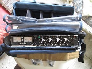
Field Mixer 4 channels SQN-4S IVe + Portabrace MXC-SQ4S + Cables and connectors
Estimated price for orientation: 890 $
Category: Live and Studio Mixers
Class:
Description
Features and Specification - SQN-4S Series IVe
Mixer Inputs
Four transformerless balanced inputs using XLR-3 type female connectors. Channels one and two also share an XLR-5 type connector. Each channel is switchable for:Powering:a)12V T (Din AB)b)12V Phantomc) 48V Phantomd) Dynamic (150 to 600 Ohms)Attenuation:0dB, -10dB or -20dB
An extra 10dB of attenuation is automatically introduced when mic powering is selected. This is achieved without compromising the noise performance of the microphone.Flat, -3dB at 75 or 105HzLine Attenuation:Adds 50dB attenuation before the mic preamp.
Sensitivity
-78dBu for nominal line level (PPM4, 0VU) with the channel gain at maximum and the master gain at 0dB
Max Level, Mic Inputs
-20dBu (+4dBu with full attenuation)
Noise Figure
-130dBu (A weighted) from a 200 Ohm source.
Frequency Response
20Hz to 20kHz +0, -1dB, referred to 1kHz.
Crosstalk
Isolation, channel to unrelated channel: 75dB at 1kHz, 60dB at 15kHz.
Channel Configuration
The mixer has four input channels, all of which have the same input selectors, bass cuts and attenuators. The routing arrangements for CH1 & 2 differ from those for CH3 & 4.
Channels 1 & 2
[GANG 1-2]
The operation of the CH1, CH2 pair is controlled by the GANG 1-2 switch on the front panel. This switch has three positions:Twin MONO [O] in which the channels are unganged and each input channel can be routed to either or both of the output channels.Stereo [S] ganging in which the Channel 1 fader controls the gain of both channels and a stereo balance control on the side panel comes into play.Mid-Side [MAT] ganging in which the Channel 1 fader controls the gain of both channels and the Channel 2 fader acts as an image width control. The incoming signal is assumed to be in MS format and is matrixed to AB. The stereo balance control remains active and will balance the matrixed signal.
Phase Switch
Channel 2 can have its phase inverted by means of a front panel switch. This has the incidental effect of interchanging left and right in an MS encoded signal.
Channels 3 & 4
The operation of the CH3, CH4 pair is much simpler than the CH1, CH2 pair. Each channel can be routed to LEFT, RIGHT or to a PANpot.
Monitor Return Input
Balanced inputs with a range of sensitivity from -20dBu to +20dBu for loudness parity with the internal monitoring. The sensitivity is adjusted by a screwdriver preset on the base.
Mixing Bus Inputs
Two inputs directly into the summing amplifiers with their gain adjustable inside the mixer. Maximum sensitivity is 0dBu for +8dBu at the balanced outputs with the master gain set at 0.
Balanced Outputs
line driver amplifiers provide the output channels and each output is available on both an individual XLR and a combined .
Output Attenuators
The level at either set of connectors can be attenuated by 50dB to provide a nominally microphone level feed.
Line Drivers
Floating sources (transformer coupled) with a clipping level of +20dBm into 600 Ohms. Distortion at the nominal peak level of +8dBm is less than 0.01% with a 600 Ohm load 20Hz to 20kHz. The output resistance is 60 Ohms.
The balanced Mic-Level sends are derived from separate windings on the output transformers. Their source impedance of 200 Ohms is essentially resistive .
Unbalanced Outputs
A connector carries separately buffered
outputs at a line level of -10dBu.
Post-Fader Outputs,
All Channels
The SUBSIDIARY I/O connector carries four buffered
outputs at a line level of -10dBu.
If an external link is made on the connector, the operation of the signal routing for channels three and four is changed so that they may be switched out of the mixing bus. Selecting PAN for CH3 or CH4 will now switch the channel out of the mix instead of to the PANpot. This is for the benefit of those who wish to extract the channels separately.
Meters
Twin peak reading, logarithmic level meters with Peak Programme Meter (PPM) dynamics. Scaling may be meters can also be provided. The meters are normally calibrated with the mixer driving a bridging load of 10k Ohms. While the mixer is operating the meters are illuminated by low power light emitting diodes. Line Output Level
The nominal line level is normally set at 0dBu for PPM metered mixers and +4dBu for VU metered mixers. Peak level, which is used as a reference for the limiters, is considered to be 8dB above this setting. Other calibration levels are readily available to order.
Output Limiters
[O]ff [M]ono [S]tereo (ganged) Attack time constant 0.5ms, release time 100ms. The limiter range is 20dB. An LED for each output channel indicates limiter action. This graph shows the entry into limiting on a steady signal for a nominal peak level of 8dBu
Line-up Tone
The Line-up tone is a sine wave at 1kHz with distortion below 0.1% which is inserted into both channels, displacing the audio output. When the [GANG 1-2] switch is in either of the ganged positions, the left hand channel tone is interrupted for 250ms every 3s. The tone switch on the front panel is a three position toggle, shared with the Slating Microphone.
Monitoring
Amplifiers with adjustable gain capable of driving most types of headphone to a suitable level. Headphones with a resistance of around 200 Ohms per side will make best use of battery power. Pre-Fade listening to each of the input channels is possible as is MS matrixing of the two output channels so that an MS recording may be monitored in the equivalent AB stereo.
Monitoring Mode Selector
The monitoring mode rotary selector switch on the front panel [PHONES] has the following functions.S StereoR Right ChannelL Left ChannelMS MS Matrix (MS stereo equivalent)L-R Left minus Right (MS stereo equivalent Right)L+R Left plus Right
(MS stereo equivalent Left or Phase Check)
Monitoring Source Selector
A front panel toggle switch selects the monitoring source as either internal [MXR] or external [AUX]
Pre-Fade Listen
A pair of front panel toggle switches selects Pre-Fade Listen for channels 1 or 2 and 3 or 4. The switches are three position, centre off.
Slating Microphone
A microphone is mounted behind the front panel near the centre of the mixer. When in use, the output of the microphone is levelled by a 2:1 compressor and displaces the normal audio, appearing on the mixer outputs and in the monitoring system. While the microphone is active, the monitoring mode automatically reverts to the internal or [MXR] setting. The Slating Microphone switch on the front panel is a three position toggle, shared with the Line-up tone.
Batteries
Eight AA size cells housed in a quick-change compartment. The acceptable range of voltages is 6 to 24 Vdc allowing the use of most cell technologies.
Battery Drain
135mA at 12 Vdc with unpowered mics. Battery life with alkaline cells will be about 10 hours.
Battery Test
The right channel meter is fitted with a suppressed-zero scale, brought into operation by a front panel push button.
External
Power
A supply in the range 6 to 24 Vdc may be used. The maximum consumption will be 2.5W and quiescent consumption, without microphones, 1.6W. The input terminals float with respect to ground. Either (or neither) side may be grounded at will, thereby allowing the use of floating supplies or grounded supplies of either polarity. There will be no possibility of hum-loops being formed.
Power Distribution
The mixer carries two four-way connectors, one of which [DC] gives access to the internal batteries for charging and also serves to connect to an external power source. The second connector [PT] is an output which provides a switched, short circuit proof connection to the power supplied to [DC]. This allows the mixer to be used as the focal point for a system of interconnected devices, all controlled from the mixer’s power switch.
Temperature Range
The mixer is designed to work over the temperature range of -20 to +60 °C.
Dimensions
The dimensions of the mixer case are: Height 47mm, Width 297mm, Depth 161mm
Construction
The outer case of the mixer is made of aluminium. The end blocks holding the connectors and the panpots are milled from solid aluminium bar. Inside the mixer is an inner compartment of steel, tin-plated after forming, which contains all of the circuitry that might be sensitive to radio frequency interference. The top and bottom of this compartment are sealed by copper screens and rf gasket material and all inputs to and outputs from this compartment are filtered. The circuitry is constructed on multi-layer printed circuit boards with internal ground and power planes which ensure the integrity of the internal grounding system.All control knobs are special to SQN and are turned and milled from solid aluminium bar. The internal battery compartment is milled and bored from a solid block of polyacetal engineering plastics material and the moving parts are aluminium and stainless steel.All labels and legends on the mixer are permanent. On the end blocks they are engraved; on the front panel they are printed into the hard-anodised surface; on the baseplate they are reverse printed on a polycarbonate label.The mechanical construction is a development of a system which has proven in the past to be resistant to mechanical damage.
Weight
The weight of the mixer without batteries is 2.2kg
Description
An extra 10dB of attenuation is automatically introduced when mic powering is selected. This is achieved without compromising the noise performance of the microphone.Flat, -3dB at 75 or 105HzLine Attenuation:Adds 50dB attenuation before the mic preamp.
[GANG 1-2]
The balanced Mic-Level sends are derived from separate windings on the output transformers. Their source impedance of 200 Ohms is essentially resistive .
outputs at a line level of -10dBu.
All Channels
outputs at a line level of -10dBu.
If an external link is made on the connector, the operation of the signal routing for channels three and four is changed so that they may be switched out of the mixing bus. Selecting PAN for CH3 or CH4 will now switch the channel out of the mix instead of to the PANpot. This is for the benefit of those who wish to extract the channels separately.
(MS stereo equivalent Left or Phase Check)
Power